
BeamLines#
BeamLine components#
A lattice branch is constructed from a BeamLine. A BeamLine is essentially
an ordered array of elements.
Each element of a BeamLine is either a lattice element or another BeamLine.
A BeamLine that is contained within another BeamLine is called a subline
of the containing BeamLine.
The top level BeamLine from which a branch is constructed is called a root Beamline.
The components of a BeamLine are:
name        # [string] Name of the BeamLine.
multipass   # [logical] Multipass line or not. Default is False.
length      # [m]: Length of the BeamLine.
line        # [list] List of elements.
zero_point  # [string] Name of a line item used as a reference point when
            #  the BeamLine is used as a subline.
periodic    # [logical] Are orbit and Twiss parameters periodic? Default is False.
The name component is a string that can be used to reference the BeamLine.
The optional multipass component is a logical describing whether the BeamLine is part of
a multipass construct. The default is False.
The optional length component gives the length of the BeamLine.
If length is not given, the BeamLine ends at the downstream end of the final
element in the line and with this the length of the BeamLine can be calculated.
The optional zero_point component is used to position sublines.
The value of zero_point is the name of a line element that marks the reference point.
To make things unambiguous, the reference line element must have zero length.
Setting optional periodic logical to true indicates that the BeamLine is something like a
storage ring where the particle beam recirculates through the BeamLine multiple times.
Setting periodic to False is used to indicate that the BeamLine is something like a
Linac or any other line that is “single pass”.
Notice that a setting periodic to true does not mean that the downstream end of
the last element of the BeamLine has the same floor coordinates as the floor
coordinates at the beginning. Setting periodic to true simply signals to a program that
it may be appropriate to calculate periodic orbits and Twiss parameters
as opposed to calculating orbits and Twiss
parameters based upon orbit and Twiss parameters set by the User for the beginning of the BeamLine.
Indeed, it is sometimes convenient to treat BeamLines as periodic even though there is no
closure in the floor coordinate sense.
For example, when a storage ring has a number of repeating “periods”, it may be
convenient, for speed reasons, to calculate the periodic functions using only use one period.
The default value of False for a given BeamLine is not affected by any
setting of periodic in any subline of the Beamline. When constructing lattice branches,
the setting of periodic in a root BeamLine can be overridden
by setting the periodic component of the branch. See Constructing a Lattice for
details.
The line component of a BeamLine holds an ordered list of items.
Each item represents one (or more if there is a repeat count) lattice element or
BeamLine.
A line item can have components
repeat          # [integer] Repetition count. Default is 1.
direction       # [switch] +1 or -1. Longitudinal orientation. Default is +1.
placement       # [struct] Shifts element or subline longitudinally.
inherit         # [string] of lattice element or subline defined outside the line
kind            # [enum] Type of element.
A line item which is an element can also have components that define the properties of the element.
For example, a MagneticMultipoleP component to define multipoles.
Example:
- thingB:
    kind: Sextupole
    length: 0.73
    ...

- inj_line:
    kind: BeamLine
    multipass: true
    length: 37.8
    zero_point: thingC
    line:
      - thingB:               # This item refers to the name of an element or BeamLine defined elsewhere.
          length: 0.45        # This instance of thingB can have differing parameter values.
      - thingZ:
          inherit: thingB     # thingZ inherits parameters from thingB
      - Q1a:                  # Define an element in place called Q1a
          kind: Quadrupole
          length: 1.03
          direction: -1
          ...
      - a_subline:            # Item a_subline is repeated three times
          repeat: 3
          ...
There are four items in the line. The second item is an element thingZ which inherits the
properties of thingB. To avoid confusion, if the inherit value is just an
unqualified element name,
what is inherited is the definition outside of any beam line.
Thus in the above example, since the inherit string is the unqualified element name thingB,
thingZ will inherit from the definition of thingB that happens before inj_line is defined
and will, for example, have a length of 0.73 meters. To inherit from the thingB which is
the first element in the line, a qualified name would have to be used. For this inj_line>>thingB
would work if thingB only appeared once in the line. In any case, inj_line>>thingB#1
(first thingB in the line) or inj_line>>1 (first item in the line) will always work even when
there are multiple thingB element in the line.
Constructing a BeamLine line#
A line item that is a lattice element can be specified by name if a lattice element of that name has been defined. Example:
- q1w:
    kind: Quadrupole
    ...

- my_line:
    kind: BeamLine
    line:
      - q1w               # Line item is element q1w.
      - q1w_01:           # q1w_01 inherits parameters from q1w
          inherit: q1w
          BodyShiftP:       #   and the parameters for q1w_01 can be modified...
          ...
      ...
A line item which is a lattice element can also be specified by defining the lattice element “in place” in the line. Example:
- a_line:
    kind: BeamLine
    line:
      - octA:              # This is a new element not previously defined.
          kind: Octupole
          MagneticMultipoleP:
            Kn3L: 0.34
          ...
    ...
A line item may be a subline:
- linac_line:
    kind: BeamLine
    line:
      ...

- main_line:
    kind: BeamLine
    line:
      - linac_line:          # linac_line is used as a subline
          direction: -1      #  parameters like reflection, etc can be used.
Restriction: Infinite recursion of sublines is not allowed.
For example, if BeamLine B is a subline of A, then BeamLine A may not be a subline of B.
Also sublines must be defined externally and not in place.
Repetition#
For any line item, a repeat count component can be used to represent multiple copies
of the item. Example:
- full_line:
    kind: BeamLine
    line:
      - short_line:
          repeat: 3
In this case, short_line is repeated three times when the BeamLine is expanded to form a lattice
branch. For example, if short_line is a beamline defined by:
- short_line:
    kind: BeamLine
    line:
      - A
      - B
      - C
then the expanded full_line will look like:
A, B, C, A, B, C, A, B, C
repetition counts can be negative. In this case, the elements are taken to occur in reverse order.
Thus, in the above example, if the repeat count was -3, the expanded full_line will
look like:
C, B, A, C, B, A, C, B, A
Notice that reverse order does not mean true direction reversal.
For elements that have longitudinal symmetry, this does not matter.
However, for example, for a Bend element that is in a line with reversed order,
the edge angle e1 will still represent the edge of the upstream side and e2 will represent the edge
at the downstream side.
Direction reversal#
The optional direction component of an item can be used for true direction reversal.
Possible values are +1 and -1. The Default is +1 which represents an unreversed element
or BeamLine. BeamLine reversal involves both reversed order of the line and direction reversal of
the individual line items. Example:
- lineA:
    kind: BeamLine
    line:
      - lineB:
          direction: -1
      ...

- lineB:
    kind: BeamLine
    line:
      - ele1
      - ele2:
          direction: -1
The expanded lineA has elements:
ele2, -ele1
where the negative sign here indicates that ele1 is reversed in direction.
Notice that ele2 is not reversed since the reversal of a reversed element results
in an element that is unreversed.
Line item placement#
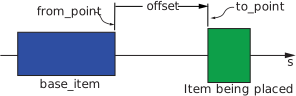
Fig. 13 Positioning of a line item (which may be a lattice element or BeamLine) with respect to
a “base” line item when there is an explicit placement component present. Assuming
unreversed elements, a positive offset positions the item being positioned downstream
of the base_item. The figure is drawn with the from_point and to_point having their
default values of EXIT_END and ENTRANCE_END respectively and assuming that the line
items are not reversed in orientation.#
By default,
a line item is placed such that the entrance end of the item is aligned with the exit end
of the preceding item as explained in the Branch Coordinates Construction section.
To adjust the longitudinal placement of an item,
the placement component of an item can be used.
When there is a placement component, figure Fig. 13 shows how the line item
is positioned with respect to a "base" line item.
The components of placement are:
offset       # Optional Real [m]. Longitudinal offset of the line item. Default is zero.
to_point     # Optional switch. Line item offset end point. Default is ENTRANCE_END.
base_item    # Optional string. Line item containing the `from_point`.
from_point   # Optional switch. Base line item offset beginning point. Default is EXIT_END.
If the base_item is not specified, the default is the previous element or the beginning
of the line if there is no previous element.
The from_point is the reference point on the base line item and to_point is the
reference point on the element being positioned. The distance between these points is set by
the value of offset.
The values of from_point and to_point can be one of the following:
ENTRANCE_END       # Entrance end of the item. Default for the `to_point` component.
CENTER             # Center of the item.
EXIT_END           # Exit end of the item. Default for the `from_point` component.
ZERO_POINT         # Used with sublines that define a `zero_point`.
Example:
- position_line:
    kind: BeamLine
    line:
      - thingA
      - extract_line:
          placement:
            offset: 37.5
            base_item: thingA
            from_point: EXIT_END
            to_point: ZERO_POINT


- extract_subline:
    kind: BeamLine
    line:
        ...
In this example, the to_point is the zero_point of extract_subline.
The from_point of thingA is placed 37.5 meters from the to_point point with
the to_point being at the exit end of thingA.
The value of offset may be negative as well as positive. With negative offsets,
the lattice expansion calculation may become recursive but, in any case, placement
must be computable. That is, situations where there is infinite recursion is forbidden.
In a section of a line where the lattice elements are not reversed, a positive offset moves
the element being placed downstream. If there is reversal, a positive offset moves
the element being placed upstream. That is, placement will not affect the relative distances
of items if a line is reversed. In the above example, if ABC_line expands to:
thingA, thingB, thingC
then the following
- z_line:
    kind: BeamLine
    line:
     - ABC_line:
         repeat: -1
Would expand to
thingC, thingB, thingA
with the same relative distances between elements. Similarly, this:
- my_line:
    kind: BeamLine
    line:
      - ABC_line:
          direction: -1
Would expand to
-thingC, -thingB, -thingA
again with the same relative distances between elements.
Lattice elements are allowed to overlap but it should be kept in mind that
some programs will not be able to handle overlapping fields.
To remove an ambiguity, if two zero length elements are next to each other in a line, the order of the
elements determines the order in which they should tracked through. For example,
if a line contains the two zero length elements:
- d_line:
    kind: BeamLine
    line:
      - markerA
      - markerB
then the order of tracking will be markerA followed by markerB.
Superposition#
The superposition construct is used to add elements to a beamline after the beamline has been defined. Superposition does not change the length of the beamline.
A superposition specifies an element to place on the beamline and a placement construct
to position the element within the beamline. Example:
- this_line:
    kind: BeamLine
    line:
      - ...
      - markerA
      - ...

- superimpose:
    place: q10w
    placement:
      base_item: markerA
      ...
In this example, the superposition places an element named q10w with respect to the
element markerA. This superposition will apply to any markerA elements that exist in
any beamline. To restrict where the superposition is applied, use the appropriate
qualified name. For example:
superimpose:
  place: q10w
  placement:
    base_item: this_line>>markerA
    ...
With this example, superposition would be restricted to markerA elements that exist in
the beamline this_line.
Superposition can be used to position elements to physically overlap other elements.
A common use case is to superimpose a Marker element in the middle of another element.
Note: superposition shares the feature of describing elements that overlap physically,
together with the UnionEle type element and the use of the
placement construct in a BeamLine.